|
|
|
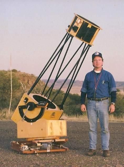
Snap shot of Yours Truly with homemade 16" f/5 Dobsonian on homemade equatorial platform at Fort Davis State Park in far West Texas in November 1998. The 'scope has since been redesigned and rebuilt. Now it's time for a major platform upgrade too! |
The Sawdust Factory Presents
VNS Equatorial Platform Making
How To Give Your Dobsonian Telescope Motorized Sky Tracking
Introduction: Just a few short decades ago, 12" (portable) telescopes were considered large by amateur astronomers due to the size of the mount required. Today, many see 18" as only medium aperture. What made the difference? The Dobsonian mount did, in a word. Named for legendary ATM John Dobson, who began popularizing it back in the 70's and early 80's, it describes an elegantly simple telescope and mount combination that suddenly made large apertures feasible for the masses. The deceptively simple mounting remains extremely popular for telescopes of all sizes to this day. But what's the price one pays for this miracle? Lack of a drive system. With a "Dob" one counteracts the Earth's rotation by nudging the telescope along by hand. Hey, it works.
Predictably enough, the ever-resourceful amateur telescope maker, or ATM in the lingo, didn't leave the lack of motor drive alone for long, and the ingenious equatorial platform soon followed. Taking the place of a massive full equatorial mounting, it is an inexpensive, easy-to-use, and very compact package that's a perfectly suited DIY project for the ATM. Unlike the computerized alt-az drive systems that began emerging about the same time, platforms offer true sidereal tracking. But what's the price one pays for this miracle? A limitation of one hour, more or less, of tracking time between resets.
Understanding how they work means getting your head wrapped around the basic theory, then the mechanical principles, and also awareness of the various types of equatorial platform arrangements, and is a longer story than a paragraph or two here can possibly deliver. Those interested in delving further into this fascinating subject are encouraged to check out the wealth of information available via the links section at the bottom of this article.
The purpose of this presentation is to document the actual fabrication process of a VNS equatorial platform, as it took place during the month of July, 2011. We're headed for the shop now, so put away the calculator and get out your safety glasses!
|
|
|
Snap shot of Yours Truly with homemade 16" f/5 Dobsonian on homemade equatorial platform at Fort Davis State Park in far West Texas in November 1998. The 'scope has since been redesigned and rebuilt. Now it's time for a major platform upgrade too! |
Where our story begins: The equatorial platform in the photo above is of the "Cylindrical Bearing" type, complete with threaded rod tangent arm drive, as developed and documented by Chuck Shaw, and also nicely documented by Warren Peters. It was fun to make, and a joy to use for ten years and more . . . . although not so much fun to haul around at 53 lbs, or reset by winding the crank.
For years I had secretly lusted after the platforms Tom Osypowski of Equatorial Platforms offers, but considered them beyond my skill range, particularly the motor drive arrangement. And since I prefer to make my own stuff wherever possible, simply ordering one from Tom wasn't an option for me. So it became a matter of waiting to be seized with a fit of enthusiastic energy sufficient to carry me through the process of figuring out how VNS platforms work, how I might devise one, and then commit to build it. It finally happened.
Note on Terminology:
Nomenclature for EQ platforms is eternally disorganized and has never been altogether agreed upon by much of anybody, we just kind of make it up as we go along. The terms, phrases, and names used in this article are my own, and therefore perfect and ought to be used by everybody. So my use of the acronym 'VNS' refers to the modified D'Autume/Alan Gee type employing conical north sectors which are mounted vertically. Thus, VNS stands for Vertical North Sector.
|
|
|
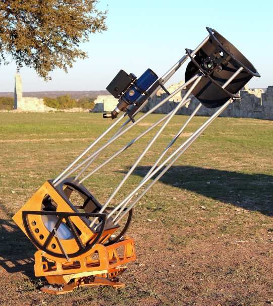
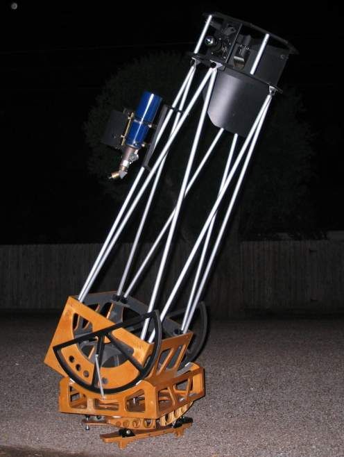
The results: a rebuilt 16" f/5 Dobsonian on a new homemade equatorial platform at Fort McKavett State Historic Site in November 2011. |
Gotta Start Somewhere
|
|
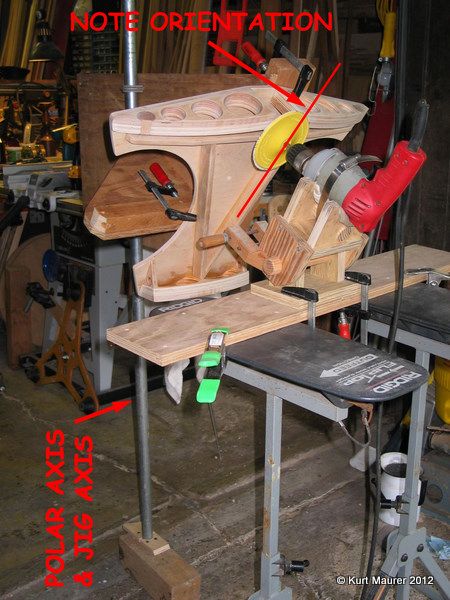
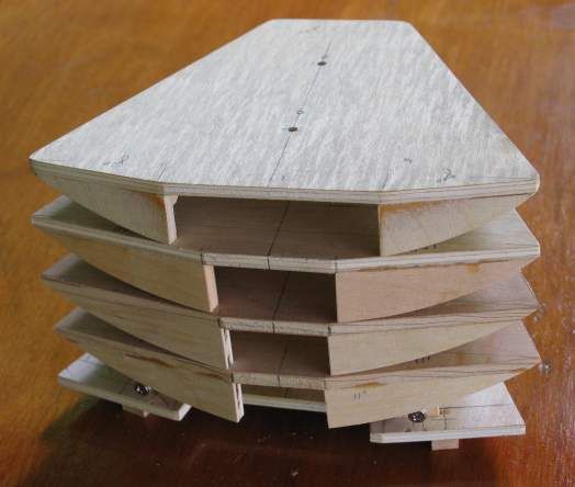
Being utterly unsure how to
proceed, I start by making a scale model to minimize time,
expense, and effort. Scale is one-third size, or 3" = 1'-0".
People often ask how I learned woodworking. By making models when I was a kid, that's how. Models are great and wonderful things, and far, far richer in educational value than they ever seem to get credit for. I could go on, but for now will just say that a pleasant hour or two in the shop playing at this little exercise makes the process clear, and gives a potent boost of much-needed confidence. . . . . . . . because at this point I'm still more than just a little mystified as to how the heck you design these things. Clearing up the mystery of how to actually make it helps a lot. Note that the model platform top plate is mounted on a jig, and the jig is mounted on a hinge representing the polar axis of rotation, which in my case, is 30 degrees. Which represents my latitude of 30 degrees north (29, actually, but no need to get quite that scientific about it). Would you like another aspirin? Here ya go. You're welcome. |
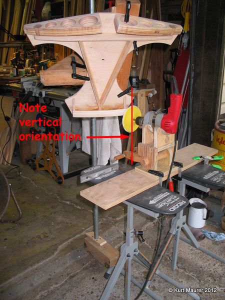
Please Note:
The north and south sectors in this type of platform are fundamentally different: the southern sector slants at a 30-degree angle, which corresponds to the latitude we are building to, and defines the motion of the thing. The two north sectors are vertical, and are what's getting sanded in the above photo. The south sector has been shaped on the vertical disc seen at lower center foreground, both operations taking place on the same jig with the hinge axis remaining vertical as shown. Yeah, I know it's weird, but keep reading and staring at the pictures and maybe it'll come into view. Or better yet, try it yourself -- I swear it's tone easier to do than (try to) explain.
| Next up is to calculate
tracking time. But "calculating" requires education, something
we obviously lack here at The Sawdust Factory. So taking the brute force
approach as usual, I once again turn
to model making. The results tell me all I need to know, or at least, make
the guesswork seem a little less far-fetched.
Each of these model top plates takes minutes to make (super glue is our friend), and all work with the bottom plate seen at the bottom of this stack. The difference between them is sector length. |
 |
Note on Terminology:
I have chosen to use the terms 'top plate' and 'bottom plate' to describe the top half, and bottom half, of the equatorial platform. So there.
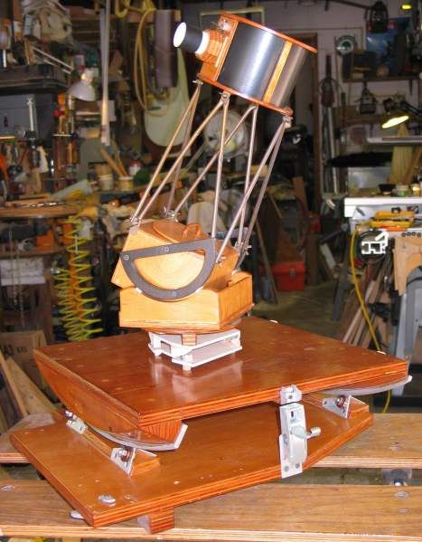
| Why looky here, I even happen to have a scale model
telescope to put on my scale model platform! Well, it's not really a scale
model, but it is a nice little 4.25" f/4 mini-Dobby that
comes close to looking correct on it.
So I pose the two together on one of the old full-size cylindrical bearing type platforms I built in the late 90's, for a fun foto. This old CB platform, by the way, is a veteran of my old 13-incher, and then served as a meteor photography platform for Robert Reeves ( Check It Out! ) for a decade or so, and was recently returned to me after having been phased out by higher tech equipment. I was in the process of putting it back into service when that long-awaited burst of enthusiasm finally surfaced, and I decided it was time to figure out and build the new platform. |
 |
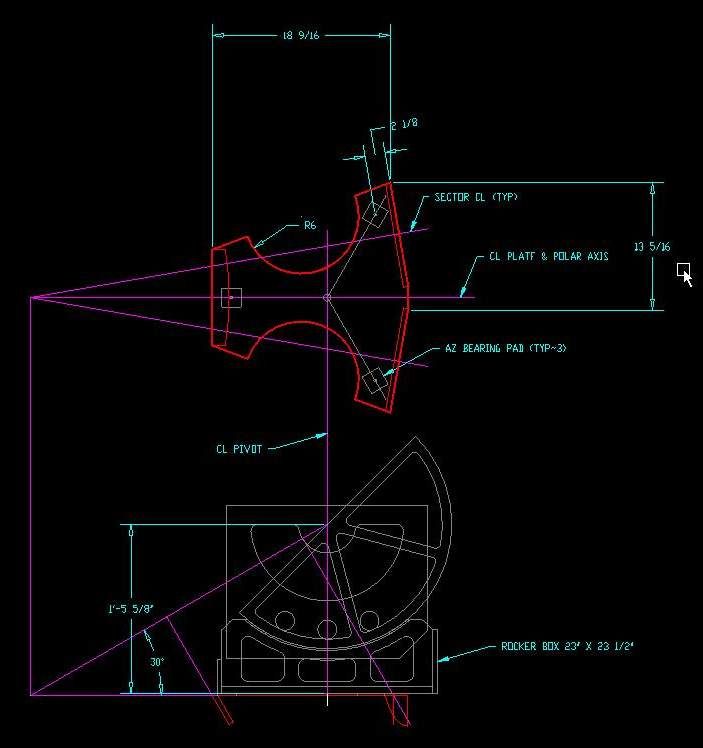
| Next thing to do is make a
drawing, so we move to the drafting table and out comes pencil and pap ...
ha ha ha, I can't even finish that sentence. Nobody draws with pencils and
paper anymore! To the computer and CAD program it is, then, and here we
use DraftSight, a very nice 2-D CAD program that closely emulates AutoCAD,
and offered free by Dassault Systemes right HERE.
Instead of writing ten tons of gobbledygook trying to explain how EQ platforms work and should be designed, I shall instead assume you've done your homework (by reading one, or better yet all, of the many existing explanations already posted on other EQ platform sites) and offer what I hope is a very helpful illustration instead. One of my personal FAQ's around here is "how did you establish the angle of the north sectors as seen from above?" Like practically everything else on these things, it all emanates from the apex of the polar cone. You know what The Cone is, right? So ideally, the sector centerlines begin at the apex, and intercept the AZ bearing pad (one of the three Teflon pads in the base of the Dobsonian telescope). But for this particular instance I've brought those centerlines inward a little in order to reduce the physical size of the finished platform. The north rollers underneath should be located on these centerlines also. |
 |
The "Hard Part" of Building Platforms: THE DREADED JIG!!
Not really. I think using a jig as shown here is actually the easiest way to arrive at accurate (enough) sectors. Others have had success with different jig approaches, but in any case, jigs just aren't that hard to manage. And the surest way to "get-r-done" is to start somewhere and tackle things one step at a time. This is the path I took.
|
|
This version of the jig consists of two parts: platform holder, and tool holder. I used a pair of flip-top adjustable stands from Home Depot to support the tool holder. They're like roller stands that assist infeed and outfeed ops on the table saw, only better built and more versatile. Every shop ought to have a pair of such stands for safety and convenience, they are often as good as, or better than, a live helper. Here, they make positioning the tool -- a drill with sanding disk in this instance -- easy and precise. Roller stands could probably be made to work as well, just remember to set the parking brake.... The platform holder is a very simple affair, look again at the model sanding jig above. This larger version is U-bolted to piece of pipe that is wedge-fitted in my garage door opening. The pipe - or hinge pin on the model - serves as the polar axis. The jig holds the platform at a 30 degree angle relative to it, at the correct distance to produce radiuses that intercept the scope's CG, blah, blah, blah. The result is accurately shaped sectors sharing a common axis of rotation. Screw math, this I can understand; and believe me, if this required anything like machinist's accuracy, we wouldn't be here talking now. Some builders hinge the platform jig to something solid, such as a door jamb. I use U-bolts to a pipe, and so am able to make multiple platforms on the same jig simply by relocating the U-bolts. This is the third I've made on this one. The polar axis pipe on the platform holder section was made plumb with a carpenter's bubble level, then the two stands were made horizontal with same. The angle of the tool was set with a 30-degree draftsman's triangle and small spirit level. Close enough!
|
|
Above: Truing the VNS, or Vertical North Sector(s). |
|
|
Some folks use sanders, others
use routers. I tried both. Verdict: I like both. But then, I jigged up the
platform and worked on the sectors multiple times, instead of just once;
more on that below.
I used the same holder for both tools. It is made from scraps of cheap plywood, pieces of closet rod, and a large hose clamp. As the drill is smaller than the router, there's a folded shop rag stuffed in as an "adapter". A good solid tool holder requires a little effort to invent and build, but is well worth the effort since it eliminates having to fight frustrating battles with half-ass kludged-together inadequate fixtures, particularly when using a router. When the desired angle set, it is simply secured with a clamp. The base of the holder is secured with a couple clamps to larger piece of scrap plywood, which in turn is clamped to the stands with spring clamps. Lots of easy and controllable adjustments can be made.
|
|
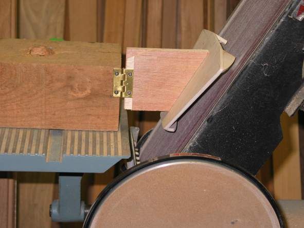
Above: Truing the south cylindrical bearing sector. |
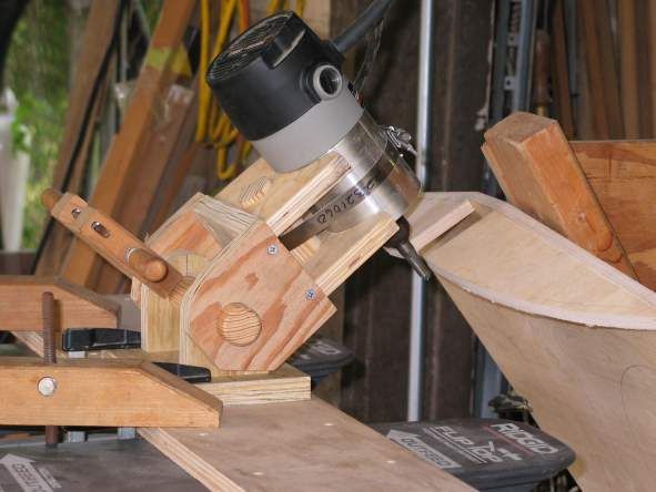
| Here's a close-up of my homemade
tool holder, this time with a router installed.
Note: When using a router, be very careful about presenting the sector-to-be to the spinning bit, for it can .... will, I mean .... "grab", and tear hell out wood if you're asleep at the wheel. Ask me how I know. |
 |
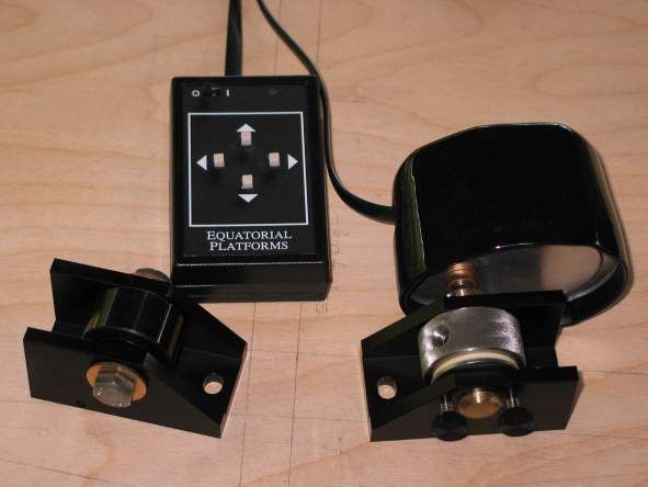
| Here is the motor and controller
I'm gonna use.
It gets pretty sad to see the best I can kludge together along the lines of electronics and motors -- hey, I'm a woodworker for crying out loud. At the other end of the spectrum, it just doesn't get much better than Tom Osypowski's stuff. It is not a cheap option literally or figuratively, but for a guy like me it is well worth it. Please note that Tom O provides no plans or instructions with his platform components. You are expected to know what to do with them, and are on your own. |
 |
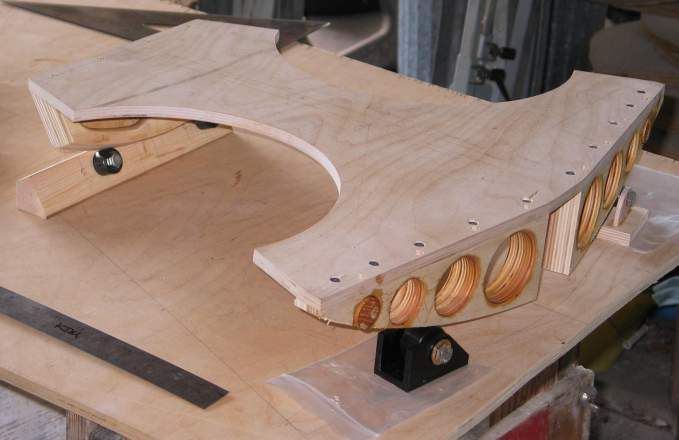 |
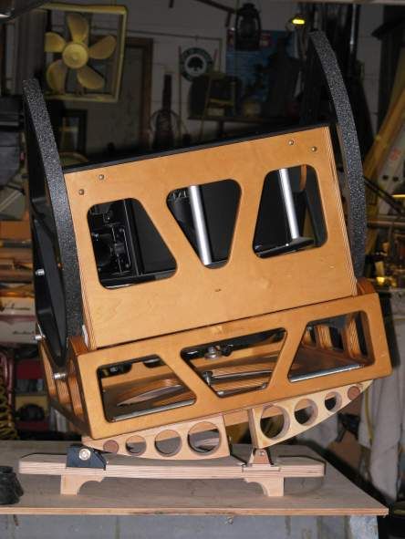
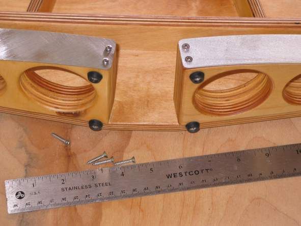
Here, we are doing several
things at once.
First and foremost, I am attempting to locate all the rollers correctly to ensure everything lines up and moves freely before drilling any holes. The temporary south roller "bracket" features holes with multiple spacings so I can try 'em all in a real-world fashion to see what works best. Also, the lightening holes in the north sectors are getting totally sealed and prepared for final finish work before being permanently installed, to make the job of sanding the insides of them ever so much easier (that's the voice of experience speaking, ladies and gentlemen). That is to say I am freely installing and detaching them right now, and will perform a final "truing up" on the jig once they are permanently glued 'n' screwed in place. Note the dummy roller I have made for the NW corner. It is a free wheeling stand-in for the more businesslike knurled motor drive wheel that makes testing the motion fun and easy. |
|
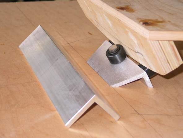
Having figured out the roller spacing on the south end, we now fashion a permanent mounting for them. Dimensions are determined by CAD drafting, cuts are made on the table saw. The material of choice is aluminum angle 2 x 2x 1/4. Shop Tip: while it may seem that metal working tools ought to be used on aluminum, in fact, woodworking tools are generally more appropriate. The aluminum is finished with a random orbital sander sporting an 80-grit pad for pretty cool looking "crackle" finish that sports kind of a hi-tech look to my eye. The top plate marking lines have been laid out in pencil on the bottom plate-to-be, in order to ensure a proper meshing of components. Only when I am satisfied that all parts are nailed down will I cut it out. Until then, I am leaving myself plenty of wiggle room, and am pretty sure I'll be needing it. |
 |
|
|
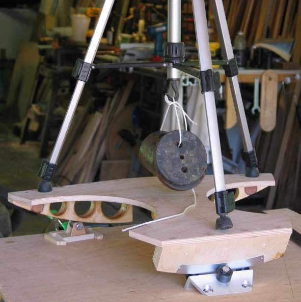
No question about it, EQ platforms are mind-benders, and if there's any one part that has been eluding me most persistently, it's how loading affects the plates, and where flex might occur. Here I have placed a photographic tripod on the platform, with its feet precisely placed on the three Teflon pad locations. Approximately twenty-five pounds of weights are attached. And now, to see what I can see.... Unfortunately, not a lot. But it was fun. |
|
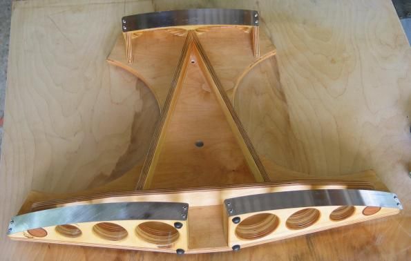
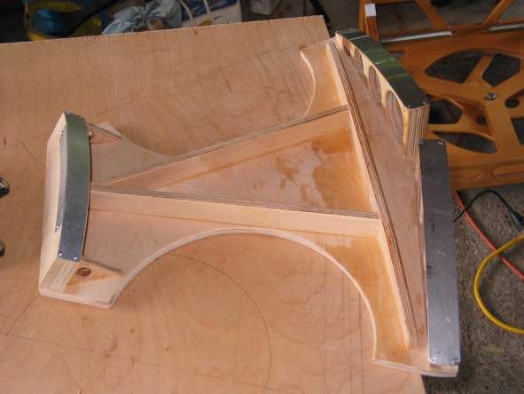
Then I got a hint: think about what happens at the extremes of travel. Another hint: the three Teflon pads are fixed to the top plate -- and the top plate moves, whereas the bottom plate feet do not. One more hint: can you say cantilever? A little light begins to flicker. More on that in just a bit, but here I have the top plate anti-flex bracing installed, and have also fitted the stainless steel north sector facings, and the aluminum south sector facings. |
 |
|
|
Okay, so it seems a few words on
sector facings may be in order.
I am advised to use stainless steel. Generally speaking, I am more accustomed to figuring this sort of thing out on my own, but since I am using components from Tom O, I feel it's wise to heed his advice, if you can imagine that. Howard Banich is another wise head I feel inclined to listen to, and he says to rough up the side with the drive roller for traction, which I have done (lower left in photo). |
| So where do you get stainless
steel strips? I'm using worn out shop rulers, and will surely enjoy the
nice new ones I pick up at the local office supply store for ~$4 apiece.
I tried using aluminum, by the way. Wasn't at all happy with it, too soft. |
 |
|
|
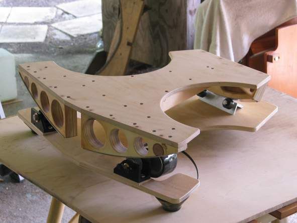
Once I am finally satisfied that all roller locations are good to go, I finally cut the bottom plate out, and zowie, an equatorial platform magically appears right before my very eyes! Now is this cool looking or what? Lotsa Screw-Ups: There have been plenty of false starts, back-stepping, and rework going on here as I get the hang of the thing, but no worries. The worst that can happen is we use filler and paint to arrive at more professional looking results. Note the feet. They're figments of your imagination. Don't for a minute imagine that I would really place them well outboard of the rollers, as seen here, and so invite an unwelcome springboard condition from the payload. They are mere props to temporarily elevate the bottom plate up off the table, that's all. |
| Ah, whew, just in the nick of
time. Here are the real
feet.
Far from an afterthought, feet are actually worth careful consideration, and they get it. And once again, I take my cue from Tom O and his highly successful product, then run it past my own shade tree engineer's eyeball because what one does for customers, and what one does for one's own self, might be two different things. Here is a system I think will work: We end up with two permanent feet up front, on the north end, and two adjustable feet on the south end. Not only does Tom do it that way, but my own thinking says that adjustment in the rear could be useful for different latitude use, and in correcting for uneven terrain. And that since there are four rollers, four feet makes sense in a load-bearing light. The aim is to get them located as nearly underneath the rollers as possible. |
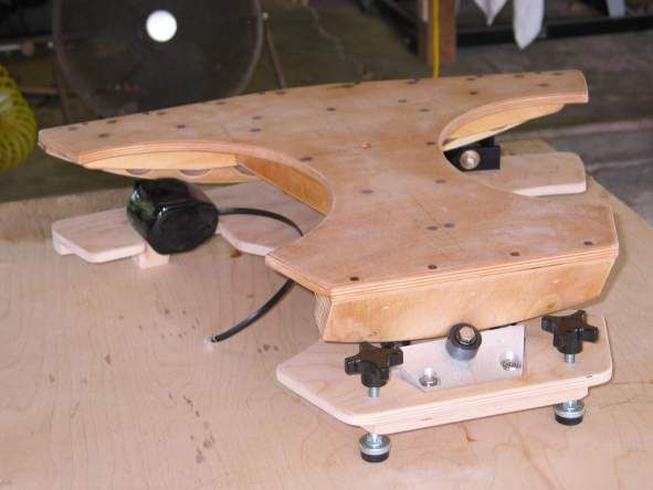 |
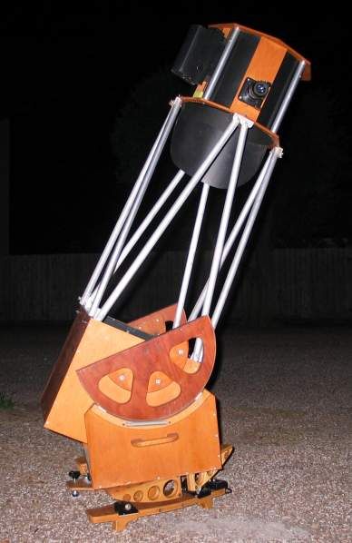
| Here are the
permanent front, or north, feet, located very nicely under the rollers.
Then we try out the general arrangement with the telescope aboard to see how it all works. This pose really shows the cantilevered loading condition at extreme end of travel I started to talk about a couple of blurbs ago. First rule: The telescope's weight goes straight down, always - gravity never takes detours. Second rule: Dobsonian mounts have the three Teflon pads located directly over the three feet on the ground board to transmit loading straight into the ground, right? But the effect of a platform is that the three pads move relative to the three feet, as this photograph very clearly illustrates. The loads on the front feet must "make a dog leg" on their way to the ground, while gravity is still going straight up and down as usual. So, the transverse, or E-W, anti-flex brace is the big deal in my mind, and the N-S ones are rather more for appearance than anything. In any case, they look good, and make dandy carry handles! |
|
|
Telescope gets a ride on the Tilt-A-Whirl machine! |
|
|
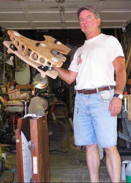
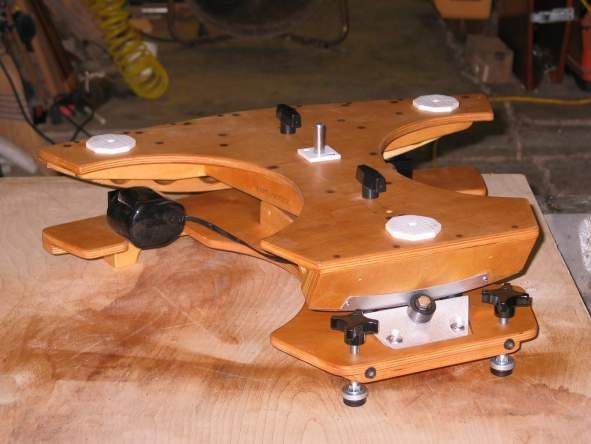
Oh yeah, now we're getting
somewhere! All components are installed together for the first time, and
we can get an idea of what the finished platform is going to be like.
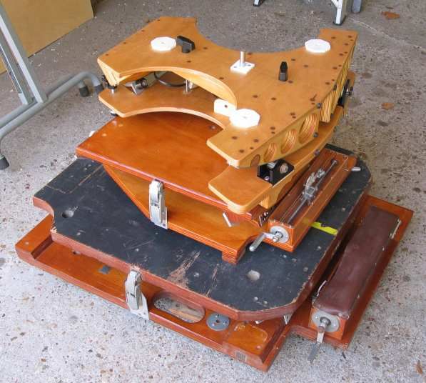
It is certainly compact enough, now let's put it on the scale and see how we did with our desire for light weight. 12 pounds. Uh huh, uh huh, I think this may work. Seen under the new platform is my old cylindrical bearing one. No way I was ever going to hold it out with one hand for a photo pose! |
| Finishing up. The wood is sealed
with marine epoxy since I happen to be a builder of canoes and kayaks, as well as
an ATM, and have it on hand.
My experience shows Baltic birch plywood to be exceedingly resistant to water incursion into the plies. Failure generally comes in the form of face veneers cracking, checking, and eventually peeling off if not refinished periodically. In my opinion, this plywood is an absolutely wonderful performer, an excellent material for us ATM's. After sealing with epoxy, a few coats of Minwax Helmsman Spar Urethane is applied from a spray can. Get it at your local hardware store. I try to get as much stuff locally as possible, but sometimes it's best to get on the net and order stuff. McMaster-Carr is the hero here, and where I generally end up for things like knobs, Teflon, leveler feet, and other assorted weird junk. |
 |
| This is my third platform so
far. It's a fraction of the size and weight of No. 1, and that's the best
part of this whole exercise right there! No. 1 also made a ladder
extension necessary for zenith viewing, and the new one does not need it.
Yippee! Platform No. 2, made for my 13-incher, suddenly caused me to need a ladder or stool for zenith viewing, which I did not care for at all. The new one allows me to observe with both feet on the ground, which I like very much! Neither platform No. 1 nor No. 2 was ever happy switching telescopes. The new one works with either equally well. No. 1 weighs 53 lbs. No. 2 weighs 19 lbs. The new one weighs 12 lbs. It just keeps getting better all the time.
|
 |
I just gotta say, I never really disliked the cranks on the old platforms. Rewinding wasn't a terrible chore, and looking down and seeing the handle turning at 2 RPM was always a vaguely reassuring sight somehow: ah, the little crank is going 'round and 'round, all is right in the universe. Looks like I'm gonna have to learn to live without 'em now, though.
|
|
The first test run, Aug 1, 2011.
The motor ran a little fast, so I slowed it down a little, blah, blah, blah. It works. |
|
|
Second test session, this time with the 13 aboard, August 2, 2011. Nuthin' to it. |
I'll add more to this saga as results come in. As it stands right now the platform got built, and initially tested, but as yet awaits routine use. I wanted to be sure to have it ready for the fall star party season, and that mission has been accomplished.
Update, 12-3-15: The ending to this story is pretty anticlimactic, kind of a no-news-is-good-news thing. It works just like advertised, as I was pretty sure it would/should, what more can ya say? I am delighted with the result, and recommend everyone build a platform, but you saw that coming, didn't you?
CLICK HERE to follow a thread on the Cloudy Nights ATM forum discussing this project!
Equatorial Platform Links
One of the first texts, if not THE first, we had for gaining an initial understanding of the Chuck Shaw Expounds
There's a very simple, very clear graphic showing the basic working principle at: Jan van Gastel's Web Site
Another excellent site to study: Reiner Vogel's take on EQ platforms
The pre-eminent commercial platform of all time: Equatorial Platforms
And another, for those "across the pond": Equatorial Platforms UK
Those who contemplate building their own need to join this Yahoo Group
I build scale models to help make concepts clear, others turn to simpler Paper Models
Return to the Sawdust Factory Table of Contents
Email Kurt Maurer at: NGC704@aol.com